Extension Cord Gauge Chart: Wire Size by Amps & Run
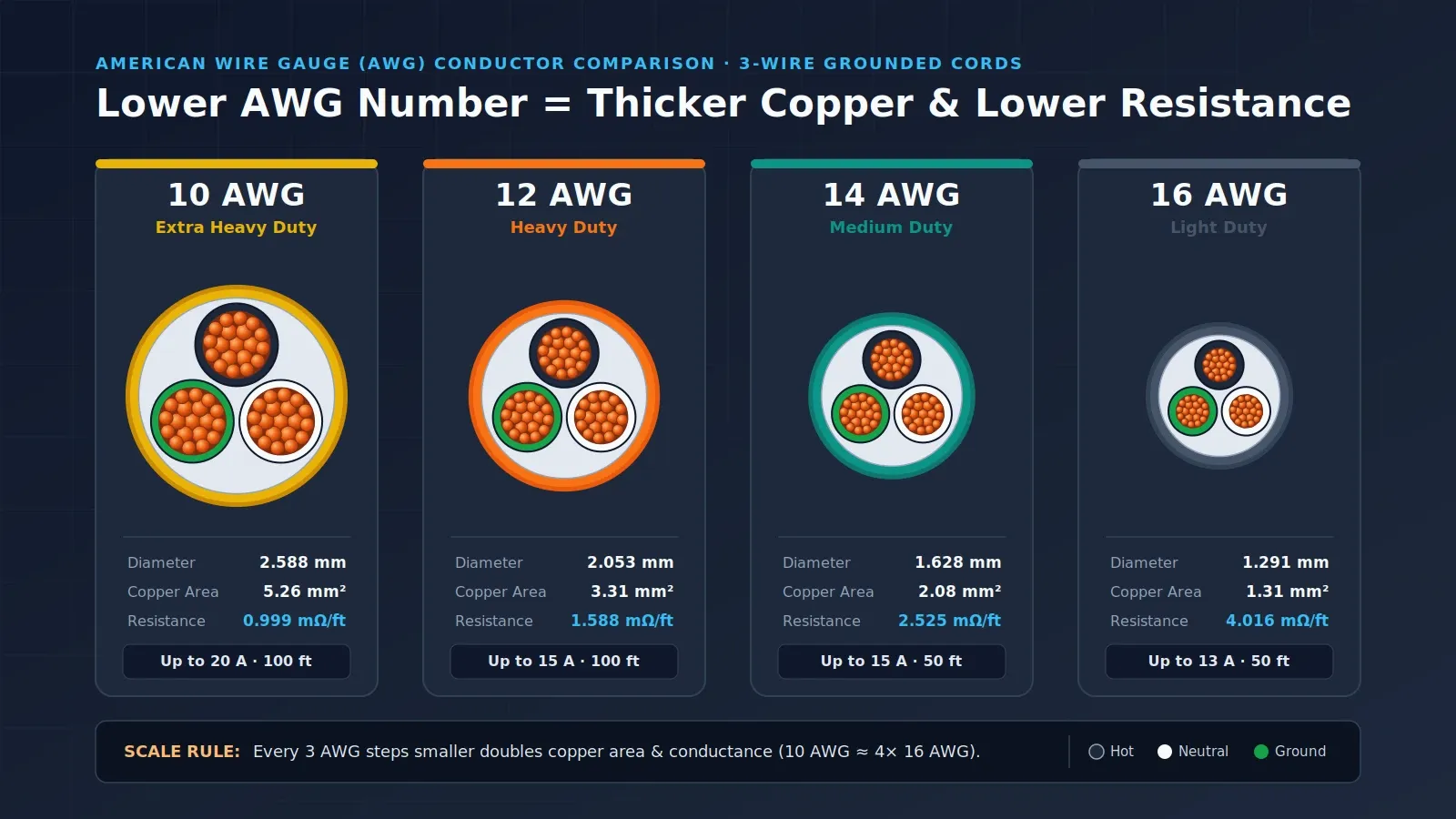
An extension cord gauge chart matches load amperage to single-cord length because lower AWG numbers carry thicker copper with lower resistance. At 50 ft, 16 AWG carries up to 7 A, 14 AWG covers 7 to 12 A, and 12 AWG handles 12 to 15 A; at 100 ft, 12 to 15 A loads require 10 AWG.
For fixture placement on temporary jobsites, pair this wire-sizing reference with our temporary construction lighting guide. When powering home or field backup circuits off an inverter, check total outlet draw in our portable power station outage circuits guide and portable power station sizing guide, or browse the full portable power and lighting hub.
What Gauge Extension Cord Do You Need for Your Load and Run Length?
Choose the minimum wire gauge where your equipment amperage column meets your total single-cord distance row, stepping down to a smaller AWG number whenever distance lengthens. As documented in UC San Diego electrical safety guidance and UC ANR Safety Note #144, a wire’s ability to carry amperage diminishes as cord length increases, so longer runs require heavier conductors to compensate for voltage drop.
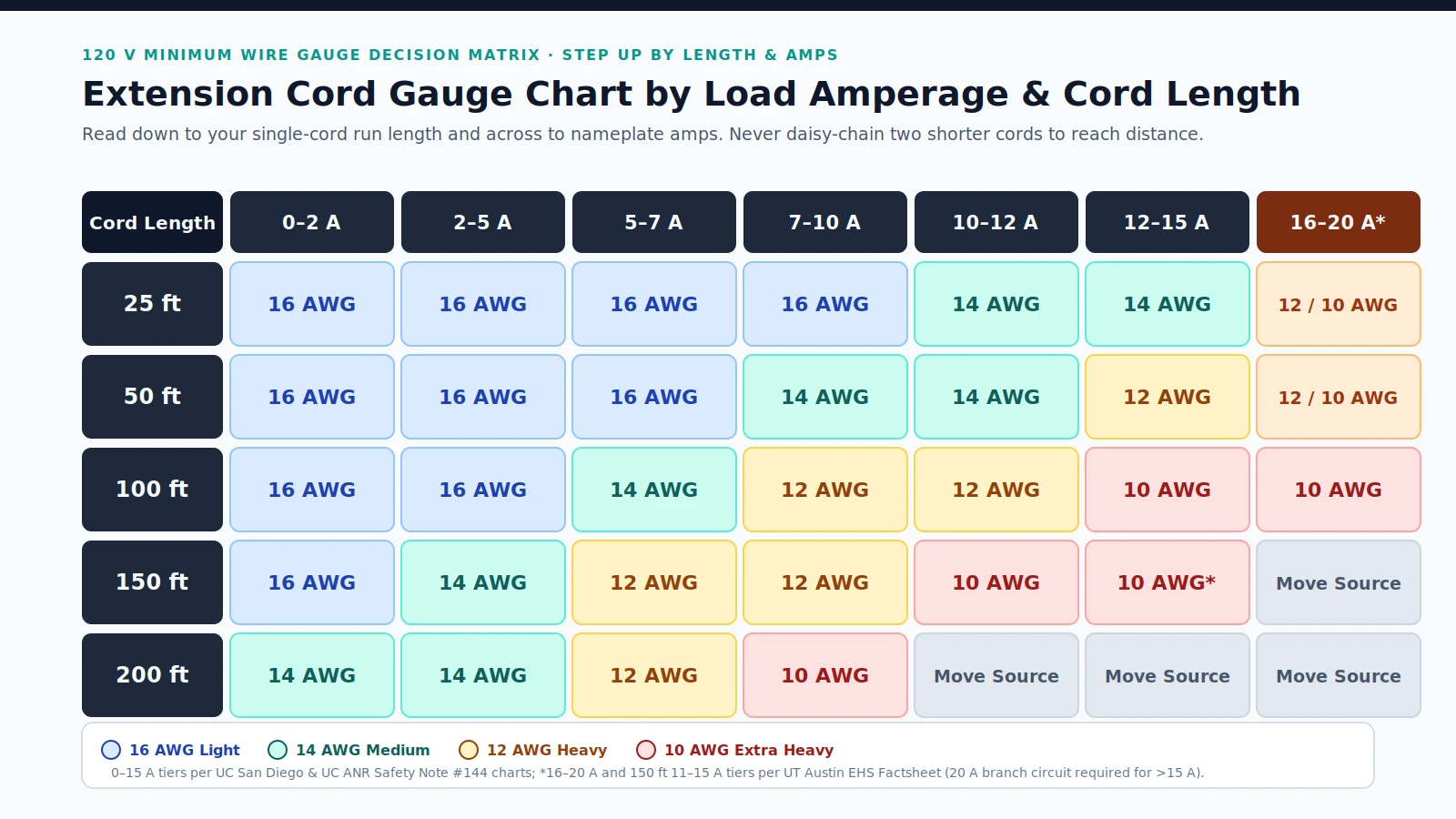
The table below combines the conservative 0 to 15 A institutional voltage-drop matrix from UC San Diego Blink with the heavy-duty 16 to 20 A and 150 ft power-tool tiers from the UT Austin Environmental Health and Safety extension cord factsheet.
Scroll horizontally to see all columns.
| Single-Cord Length | 0–2 A | 2–5 A | 5–7 A | 7–10 A | 10–12 A | 12–15 A | 16–20 A (20 A Circuit) |
|---|---|---|---|---|---|---|---|
| 25 ft | 16 AWG | 16 AWG | 16 AWG | 16 AWG | 14 AWG | 14 AWG | 12 AWG or 10 AWG |
| 50 ft | 16 AWG | 16 AWG | 16 AWG | 14 AWG | 14 AWG | 12 AWG | 12 AWG or 10 AWG |
| 100 ft | 16 AWG | 16 AWG | 14 AWG | 12 AWG | 12 AWG | 10 AWG | 10 AWG |
| 150 ft | 16 AWG | 14 AWG | 12 AWG | 12 AWG | 10 AWG | 10 AWG (UT Austin 11–15 A) | Relocate power source |
| 200 ft | 14 AWG | 14 AWG | 12 AWG | 10 AWG | Relocate power source | Relocate power source | Relocate power source |
How to Read Nameplate Amps and Avoid Undersizing
Before pulling a cord from the truck, verify three checks directly on the equipment and cord jacket:
- Read the wire marking: According to UC San Diego electrical safety guidance, wire thickness is printed as AWG followed by the gauge and conductor count, so AWG 12-3 means three 12 AWG wires inside the jacket.
- Match or exceed the appliance cord: Keep the extension cord conductor diameter at least as large as the cord attached to the tool or fixture plugged into it.
- Apply the 100 ft step-up rule: UC ANR Safety Note #144 advises stepping up one heavier wire gauge for every 100 ft of additional cord length and warns against connecting two or more cords together to gain reach.
Which Is Thicker, a 12-Gauge or 14-Gauge Extension Cord?
A 12-gauge extension cord is substantially thicker than a 14-gauge cord because American Wire Gauge (AWG) numbers decrease logarithmically as conductor diameter grows. Specifically, 12 AWG copper measures 2.053 mm (0.0808 in) in diameter with 3.31 mm² of copper area and 1.588 mΩ/ft of resistance, whereas 14 AWG measures 1.628 mm (0.0641 in) with 2.08 mm² of area and 2.525 mΩ/ft of resistance.
As detailed in American wire gauge conductor specifications, two geometric rules govern every jump between cord gauges:
- Three-gauge rule: Decreasing the AWG number by 3 doubles conductor cross-sectional area and doubles electrical conductance.
- Six-gauge rule: Decreasing the AWG number by 6 doubles solid wire diameter and quadruples both cross-sectional area and conductance—for example, moving from 16 AWG to 10 AWG.
Stranded flexible cords use the cross-sectional area of the equivalent solid copper conductor to set their AWG size, while small gaps between circular strands make the overall stranded bundle slightly wider than a solid wire of the same gauge.
Scroll horizontally to see all columns.
| Wire Gauge (AWG) | Solid-Equivalent Diameter (in) | Solid-Equivalent Diameter (mm) | Copper Area (mm²) | Copper Resistance (mΩ/ft) | Copper Resistance (mΩ/m) |
|---|---|---|---|---|---|
| 8 AWG | 0.1285 in | 3.264 mm | 8.37 mm² | 0.6282 mΩ/ft | 2.061 mΩ/m |
| 10 AWG | 0.1019 in | 2.588 mm | 5.26 mm² | 0.9989 mΩ/ft | 3.277 mΩ/m |
| 12 AWG | 0.0808 in | 2.053 mm | 3.31 mm² | 1.588 mΩ/ft | 5.211 mΩ/m |
| 14 AWG | 0.0641 in | 1.628 mm | 2.08 mm² | 2.525 mΩ/ft | 8.286 mΩ/m |
| 16 AWG | 0.0508 in | 1.291 mm | 1.31 mm² | 4.016 mΩ/ft | 13.17 mΩ/m |
| 18 AWG | 0.0403 in | 1.024 mm | 0.823 mm² | 6.385 mΩ/ft | 20.95 mΩ/m |
For work lighting and field tools running over 50 ft, comparing a 12-gauge vs 14-gauge extension cord comes down directly to that resistance gap: dropping from 2.525 mΩ/ft on 14 AWG to 1.588 mΩ/ft on 12 AWG cuts resistive voltage loss across the full round-trip conductor path.
What Is the Safe Amp Rating for a 14-Gauge Extension Cord?
Under UL 817 and NEC extension cord ratings, a 14/3 extension cord carries a maximum rating of 15 A at 50 ft (15 m), dropping to 13 A at 100 ft (30 m). Under stricter institutional voltage-drop limits from UC San Diego Blink, 14 AWG is rated for 10 to 15 A at 25 ft, 7 to 12 A at 50 ft, 5 to 7 A at 100 ft, 2 to 5 A at 150 ft, and up to 5 A at 200 ft.
Why two reputable tables set different ceilings for the same cable:
- Cord-set maximum current (UL 817 / UL 62): Sets the upper thermal current limit printed on retail packaging: 15 A at 50 ft and 13 A at 100 ft for 14/3, compared with 13 A at 50 ft and 10 A at 100 ft for 16/3.
- Distance-derated field sizing (UC San Diego / UC ANR): Steps 14 AWG down earlier as distance increases so motors, LED drivers, and portable equipment do not suffer excessive voltage drop along 100 ft or 150 ft runs.
For 14 to 15 A loads at 25 ft such as lawn mowers, power drills, or table saws, the UT Austin EHS factsheet permits 14 AWG medium-duty cord. Once the same 12 to 15 A load stretches to 50 ft, moving up to 12 AWG avoids operating a 14 AWG cord right against its upper rating.
When Should You Step Up From a 12-Gauge to a 10-Gauge Extension Cord?
Step up from 12 AWG to 10 AWG whenever a 12 to 15 A load reaches 100 ft, a 10 to 15 A load stretches to 150 ft, a 7 to 10 A load reaches 200 ft, or a 16 to 20 A heavy load runs at 100 ft. Replacing 12 AWG (3.31 mm², 1.588 mΩ/ft) with 10 AWG (5.26 mm², 0.9989 mΩ/ft) significantly expands copper cross-section and curbs voltage loss over long distances.
Compare the exact step-up triggers across UC San Diego, UT Austin EHS, and UL/NEC cord-set ratings:
- 12 to 15 A at 100 ft: While a 12/3 cord retains a 15 A nominal UL rating out to 100 ft (30 m), UC San Diego’s voltage-drop chart steps 12 to 15 A loads up to 10 AWG at 100 ft to hold voltage stability at the tool end.
- 10 to 15 A at 150 ft: At 150 ft, UC San Diego requires 10 AWG for 10 to 12 A loads, and UT Austin EHS specifies 10 AWG extra-heavy-duty cord for 11 to 15 A saws and shop vacs.
- 7 to 10 A at 200 ft: Even moderate lighting or pump loads drawing 7 to 10 A require 10 AWG once distance reaches 200 ft; loads above 10 A at 200 ft exceed standard chart coverage and require relocating the power source closer to the work area.
- 16 to 20 A at 100 ft: For 16 to 20 A equipment such as air compressors running 100 ft from a 20 A receptacle, UT Austin EHS specifies 10 AWG extra-heavy-duty cord rather than 12 AWG.
What Extension Cord Gauge Is Needed for High-Draw Power Tools?
High-draw power tools drawing 14 to 15 A require at least 12 AWG at 50 ft and 10 AWG at 100 to 150 ft, while 16 to 20 A chain saws, circular saws, and air compressors require 12 AWG or 10 AWG at 25 to 50 ft and 10 AWG at 100 ft. At 120 V in the United States, the National Electrical Code prohibits extension cords on 20 A circuits unless conductors are 16 AWG or thicker, and OSHA requires three-wire hard or extra-hard usage cords for construction tools.
Match common jobsite tools and lighting loads to verified institutional recommendations from UT Austin EHS and UC San Diego Blink:
Scroll horizontally to see all columns.
| Load Tier & Example Equipment | 25 ft Run | 50 ft Run | 100 ft Run | 150 ft Run |
|---|---|---|---|---|
| Light duty: work lights, portable fans, hedge trimmers (1–7 A) | 16 AWG | 16 AWG | 14 AWG (5–7 A) | 12 AWG (5–7 A) |
| Medium tools: power drills, lawn mowers, light table saws (10–12 A) | 14 AWG | 14 AWG | 12 AWG | 10 AWG |
| Heavy 15 A tools: circular saws, table saws, shop vacs (12–15 A) | 14 AWG | 12 AWG | 10 AWG (12 AWG UT Austin 14–15 A) | 10 AWG |
| Extra-heavy 20 A tools: air compressors, heavy saws (16–20 A) | 12 AWG or 10 AWG | 12 AWG or 10 AWG | 10 AWG | Relocate power source |
Under OSHA 29 CFR 1926.405, extension cord sets powering portable electric tools and appliances on construction sites must be three-wire grounded cords designed for hard or extra-hard usage, and flexible cords supplying temporary or portable lights must also meet hard or extra-hard usage standards. When budgeting portable lighting loads alongside tool runs, check fixture draw in our portable work light buying guide.
Why Do Long Outdoor Runs Require Jacket Code and Field Hazard Checks?
Long outdoor runs combine elevated resistive voltage drop with weather exposure, moisture leakage, mechanical crushing, and coiled-reel heat buildup. Even when the copper AWG matches the chart, using an indoor jacket outdoors, daisy-chaining two cords, leaving excess length coiled under load, or pinching a cable in a doorway can overheat insulation or create a shock hazard.
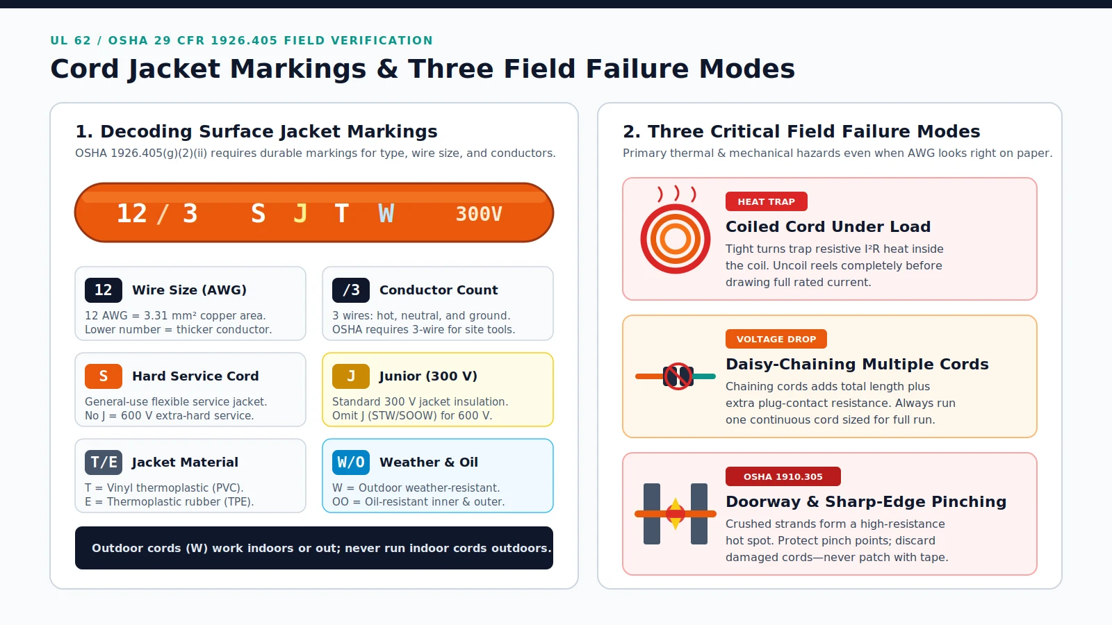
Under OSHA 29 CFR 1926.405, type SJ, SJO, SJT, SJTO, S, SO, ST, and STO cords cannot be used on construction sites unless durably marked on the jacket surface with the type designation, wire size, and number of conductors. As explained by UT Austin EHS and UL 62 cable markings, every letter on the jacket defines a specific physical boundary:
Scroll horizontally to see all columns.
| Jacket Letter or Code | Published Meaning | Outdoor Field Guidance |
|---|---|---|
| S | General-use flexible hard service cord | Baseline service rating required for worksite tools and lights |
| J | Junior hard service with standard 300 V insulation | Omitting J (such as STW or SOOW) indicates thicker 600 V insulation for heavier use |
| W | Rated for outdoor weather-resistant use | Outdoor W cords work indoors or outdoors; never run indoor cords outside |
| T | Vinyl thermoplastic (PVC) outer jacket | Standard outdoor jacket material (such as SJTW) |
| E | Thermoplastic elastomer rubber (TPE) jacket | Flexible rubber-style thermoplastic jacket alternative to PVC |
| O / OO | Oil-resistant insulation or jacket | SJOOW provides both oil-resistant inner conductor insulation and an oil-resistant outer jacket |
| P | Parallel wire construction | Used in household and air conditioner cords rather than round hard-service jobsite cords |
Voltage Drop, Coiled Reels, and Daisy-Chaining
Under Ohm’s law voltage drop principles, resistive voltage drop across a DC conductor equals current multiplied by resistance (V = I R), while AC circuits add reactance as impedance (E = I Z). That voltage drop occurs across conductors, contacts, and connectors, dissipating part of the supplied electrical energy as heat.
Three deployment habits turn normal conductor resistance into fire and failure hazards—contributing to the roughly 3,300 residential fires, 50 deaths, and 270 injuries per year that CPSC estimates cited in UC ANR Safety Note #144 attribute to extension cord short circuits, overloading, damage, and misuse:
- Coiling excess cord under load: As explained in extension cord reel safety guidance, an extension reel carries its full rated current only when completely extended; tightly coiled layers prevent resistive heat from dissipating into air, creating shock and fire hazards.
- Daisy-chaining multiple cords: Both UC San Diego and UC ANR Safety Note #144 prohibit linking two or more extension cords end-to-end. Select a single continuous cord long enough for the full distance.
- Ignoring plug and jacket temperature: While noticeable warming can occur at maximum rated load, UC ANR Safety Note #144 states that a hot cord body or plug or softening plastic signals a fault requiring immediate de-energization and disposal.
Pinch Points, Wet Connectors, and OSHA Field Inspection Checks
Mechanical protection and moisture control matter just as much as wire thickness on active sites. Under OSHA 29 CFR 1910.305, flexible cords and cables must be protected from accidental damage caused by sharp corners, projections, doorways, and other pinch points. Crushing a cord in a door narrows intact internal wire strands into a high-resistance constriction where power dissipation concentrates into a localized hot spot.
Before energizing temporary site lighting or backup power runs, walk every cord against this verification table:
Scroll horizontally to see all columns.
| Field Check Item | Requirement & Threshold | Failure Mode Prevented |
|---|---|---|
| Jacket markings & grounding | Durably marked 3-wire hard-service cord (such as SJTW or SJOOW); third ground prong intact | Eliminates ungrounded shock risk and loss of hot/neutral polarization |
| Continuous unspliced length | Single continuous cord; under 29 CFR 1926.405, repair splices apply only to hard service No. 12 or larger retaining original properties | Prevents taped field splices and weak insulation joints |
| Strain relief & physical damage | Intact strain relief so pull never transfers to terminal screws; discard frayed cords rather than wrapping electrical tape | Stops concealed conductor damage, arcing, and short circuits |
| Routing & pinch protection | Keep clear of doorways, sharp corners, staples, carpets, and uncovered vehicle paths; fully uncoil reels | Prevents crushed-strand hot spots and trapped coil heat |
| Wet & conductive locations | Use watertight or sealable connectors; run portable lighting in wet/conductive zones at 12 V or less, or 120 V with GFCI protection | Prevents current leakage across wetted connector surfaces |
Frequently Asked Questions
How much lower is copper resistance in 12 AWG compared with 14 AWG?
A 12-gauge extension cord is thicker and carries substantially less resistance. Under American Wire Gauge rules, smaller numbers denote larger conductors: 12 AWG has a 2.053 mm (0.0808 in) diameter, 3.31 mm² copper area, and 1.588 mΩ/ft resistance, whereas 14 AWG has a 1.628 mm (0.0641 in) diameter, 2.08 mm² area, and 2.525 mΩ/ft resistance.
Why do UL 817 cord-set ratings and institutional voltage-drop charts differ for 14 AWG?
Under UL 817 and NEC cord-set ratings, a 14/3 extension cord is rated up to 15 A at 50 ft (15 m) and drops to 13 A at 100 ft (30 m). Under conservative institutional voltage-drop charts from UC San Diego and UC ANR, 14 AWG is recommended for 10 to 15 A at 25 ft, 7 to 12 A at 50 ft, and 5 to 7 A at 100 ft.
What length and amperage thresholds require stepping up to 10 AWG?
Choose 10 AWG (5.26 mm², 0.9989 mΩ/ft) over 12 AWG (3.31 mm², 1.588 mΩ/ft) when running 12 to 15 A loads at 100 ft, 10 to 15 A loads at 150 ft, 7 to 10 A loads at 200 ft, or 16 to 20 A equipment such as air compressors at 100 ft.
Can you plug two extension cords together to reach 100 feet?
No. Both UC San Diego electrical safety rules and UC ANR Safety Note #144 prohibit linking or daisy-chaining extension cords. Use a single continuous cord long enough for the full distance and sized one gauge heavier per 100 ft of added run.
Why must an extension cord reel be fully uncoiled under load?
An extension reel carries its full rated current only when completely extended. Leaving turns tightly wound on a reel traps resistive heat inside the coil where air cannot cool it, creating a serious overheating, shock, and fire hazard.
Sources and versions
- Electrical Safety: Extension Cords , UC San Diego Blink Supports: Extension cord gauge selection matrix from 25 ft to 200 ft across 0–15 A brackets, AWG 12-3 marking meaning, indoor vs. outdoor rule, and prohibition on daisy-chaining.
- Factsheet: Extension Cords , University of Texas at Austin Environmental Health and Safety Supports: Heavy-duty cord selections, UL/NEC cord jacket letter definitions (S, W, J, P, T, E, O), OSHA hard-usage markings, and wet connector leakage precautions.
- Safety Note #144: Electrical Extension Cord Safety , University of California Agriculture and Natural Resources (UC ANR) Supports: CPSC annual extension cord fire estimates (3,300 residential fires, 50 deaths, 270 injuries), 100 ft gauge step-up rule of thumb, electrical tape prohibition, and plug heat inspection.
- 29 CFR 1910.305 — Wiring methods, components, and equipment for general use , Electronic Code of Federal Regulations (eCFR) Supports: OSHA general industry requirement to protect flexible cords and cables from accidental damage at sharp corners, projections, doorways, and other pinch points.
- 29 CFR 1926.405 — Wiring methods, components, and equipment for general use (Construction) , Electronic Code of Federal Regulations (eCFR) Supports: OSHA construction mandates for three-wire hard or extra-hard usage cords, durable surface markings, continuous unspliced lengths (with No. 12 repair rule), strain relief, and wet-location GFCI lighting.
- American wire gauge , Wikipedia Supports: Logarithmic inverse AWG geometry, 3-gauge and 6-gauge conductance rules, stranded conductor sizing, and copper wire diameters, cross-sectional areas, and resistance values.
- Extension cord , Wikipedia Supports: NEC 16 AWG minimum on 120 V 20 A circuits, UL 817 and UL 62 cord standards, 16/3, 14/3, 12/3, and 10/3 current ratings at 50 ft and 100 ft, SJTW and SJOOW designations, coiled reel heat trapping, and crushed-conductor hot spots.
- Voltage drop , Wikipedia Supports: Definition of voltage drop across conductors, contacts, and connectors, Ohm's law resistive voltage drop (V = I R), and AC circuit impedance voltage drop (E = I Z).
Next steps
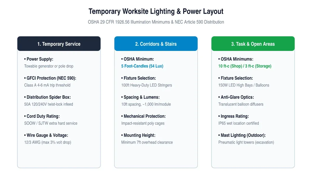
Temporary Construction Lighting: OSHA Requirements and Worksite Power
A technical guide to temporary construction lighting: OSHA minimum illumination standards (29 CFR 1926.56), string lights vs high bay vs balloon diffusers, GFCI distribution, and generator sizing.
Portable Power Station for Home Backup: Appliance Startup Checks, Duty Cycles, and Corded Load Limits
Plan a portable power station for home backup: check appliance surge demand, refrigerator duty cycles, cord limits, and your outage load worksheet.
How to Size a Portable Power Station for Outdoor Work
Size a portable power station for outdoor work: list loads, check continuous and surge watts, estimate watt-hours from the hours and the loss and reserve you write down, and verify charging.

Portable Work Lights: A Buying Guide for Outdoor Teams
How outdoor teams can compare portable work lights: lumens vs lux, beam pattern, runtime claims, mounting, protection ratings, plus a supplier comparison sheet.