Work Light LED Output: Lumens, CRI, and Beam Angle
A larger lumen rating fails when the beam misses the work plane. The wasted light still costs runtime on a battery pack.
Scroll horizontally to see all columns.
| Figure | What a published value measures | Dominant failure mode | Prevention |
|---|---|---|---|
| Lumens (lm) | Total flux leaving the product in one stated mode | Using a cold, chip, or unnamed-mode number as task light | Record mode, supply, and the measurement method |
| Lux (lx) | Flux arriving per square meter | Comparing lux numbers taken at different distances | Keep the distance and the aiming with the number |
| Beam angle | Full angle between the 50% intensity directions | Treating the angle as a hard edge that contains every lumen | Calculate the contour diameter, then expect light outside it |
| CRI | Average color shift versus a reference at a similar CCT | Ranking CRI across very different color temperatures | Compare near the same CCT and check saturated reds when they matter |
| CCT (K) | Appearance of the light itself, warm to cool | Assuming a higher kelvin number means better color fidelity | Read CCT beside CRI, not instead of it |
| Supply and mode | Which input and which output setting the runtime belongs to | Copying the high-mode lumen number onto the AC line or the low setting | Give each supply and each setting its own row |
The work light buying guide collects those rows into a supplier sheet. This page is the arithmetic behind three of them.
Lumens that leave the lamp are not lux on the work
NIST’s conversion table gives the factor that turns a foot-candle requirement into lux. Both “footcandle → lux” and “lumen per square foot → lux” are listed as 1.076 391 × 10¹, so:
1 footcandle = 10.76391 lx
OSHA 29 CFR 1926.56, Table D-3, states minimum illumination while work is in progress. The row that names field maintenance areas, together with concrete placement, excavation, waste areas, access ways, active storage, loading platforms and refueling, is 3 foot-candles. General construction area lighting is a separate row at 5 foot-candles. General construction plant and shops, including mechanical and electrical equipment rooms, are 10 foot-candles. First aid stations, infirmaries and offices are 30. Match the operation before converting. Five foot-candles is 5 × 10.76391 = 53.82 lx, which rounds to 54 lx. A rounded table can print 54 without using a different physical unit.
Delivered flux on a surface is illuminance times area:
Φ_delivered = E × A
E is in lux and A is in square meters. The product is in lumens, because the NIST factor treats the lux as the SI partner of the lumen per square foot, and the international foot is listed on the same page as 3.048 × 10⁻¹ meter.
Worked example, field maintenance row, not a product recommendation. Take 3 foot-candles on a 4.0 m by 3.0 m zone.
E = 3 × 10.76391 = 32.29173 lx
A = 4.0 × 3.0 = 12 m²
Φ_delivered = 32.29173 × 12 = 387.5 lm
Those 387.5 lm have to land on the 12 m². They are not a catalog rating. Light that falls outside the zone, and light lost between the lamp and the plane, is extra flux the fixture must emit. OSHA does not publish that extra fraction, and a beam angle does not publish it either. A lux meter on the plane, or a photometric file for the exact mode, is the check. The temporary construction lighting guide is the place for the rest of the Table D-3 layout.
The same formula shows why a small color-critical panel is a different problem. An electrical equipment room is on the 10 foot-candle row, not the 3 foot-candle row. On a 0.60 m by 0.40 m panel:
E = 10 × 10.76391 = 107.6391 lx
A = 0.60 × 0.40 = 0.24 m²
Φ_delivered = 107.6391 × 0.24 = 25.8 lm
Twenty-six lumens on the panel can satisfy that minimum and still come from a fixture rated in the thousands, if most of the beam misses the panel. The minimum is also only a minimum. Identifying conductor colors is a harder visual task than walking the zone, which is why CRI is the next section rather than a larger lumen number.
Beam angle is the 50% contour
The Illuminating Engineering Society defines beam angle as the angle between the two directions for which intensity is 50% of the maximum, measured in a plane through the nominal beam centerline. Beams without rotational symmetry are generally given in two planes at 90°, the maximum and the minimum. The definition notes that some fields used to measure to 10% of maximum instead. ENERGY STAR’s lamps specification, citing ANSI C78.379-2006, uses the same 50% idea: the full angle between opposite directions at 50% of center-beam intensity, in at least two rotational planes 90° apart.
For a rotationally symmetric beam, the contour diameter on a plane perpendicular to the axis is:
D = 2 × H × tan(θ / 2)
H is the distance along the beam axis. θ is the published full beam angle.

Worked example at H = 2.00 m. For θ = 60°, half-angle is 30° and tan(30°) = 0.577350.
D = 2 × 2.00 × 0.577350 = 2.31 m
For θ = 120°, half-angle is 60° and tan(60°) = 1.732051.
D = 2 × 2.00 × 1.732051 = 6.93 m
6.93 / 2.31 = 3, so the contour area, which scales with D², is 3 × 3 = 9 times larger. The same flux spread over nine times the contour area delivers about one ninth the average illuminance inside that contour, and only under the extra assumption that the lumens inside the two contours are equal. They are not automatically equal: the contour is a 50% intensity locus, and real flux continues outside it.

Doubling H at a fixed θ doubles D and multiplies contour area by four. Average illuminance inside the contour falls toward one quarter only when the flux inside the contour stays the same. Aiming, a lens change, or a different mode breaks that assumption.
Rule of thumb: if the published beam angle exceeds 90° at a mounting distance of 2.00 m, the 50% contour is wider than 4.00 m. At 90°, tan(45°) = 1, so D = 2 × H = 4.00 m. A panel of about 0.6 m does not fill that contour. Use a narrower published angle, or move the lamp closer, and keep the task out of the glare of a wide flood. Mounting and aiming sit in the maintenance task light guide.
CRI does not travel across color temperature
The Department of Energy’s January 2012 LED Color Characteristics fact sheet (PNNL-SA-84900) describes CRI as the average of the color-shift scores Ri for eight standard test colors, usually from 0 to 100. A score of 100 means the source matches the reference. The fact sheet’s rough interior scale is: CRI in the 70s acceptable, the 80s good, the 90s excellent. It also says two sources with the same CCT and the same CRI can still render colors differently, and that CRI is a weak predictor once white LEDs are in the set. Treat the 70 / 80 / 90 bands as that fact sheet’s guideline, not as a work-light pass-fail law.
The reference changes with CCT. The fact sheet’s footnote specifies blackbody radiation below 5000 K and a mathematical model of daylight at higher CCTs. Comparing CRI for sources of very different CCTs is, in the fact sheet’s words, something to do only with great caution, and it is not appropriate across that reference change.
Rule of thumb: if one published CCT is below 5000 K and the other is 5000 K or above, do not pick the higher CRI. The references are different. Read the two CCTs first.
R9 through R14 are special indices. They are not inside the CRI average. The fact sheet says an R9 above 0 is generally considered acceptable for the strong-red sample, with the warning that the underlying color space exaggerates red shifts. Conductor insulation and paint marks are closer to that problem than a pastel test color is. When the task is color-critical, the fact sheet’s own close is the right one: obtain more than CRI and CCT from the manufacturer, and look at the actual surface. There is no substitute, in that fact sheet, for visual evaluation on a critical purchase.
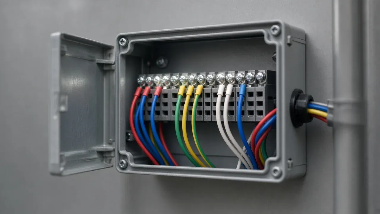
A neutral-white marketing line is not a CCT and not a CRI. If the sheet does not print kelvin and a CRI method, leave those cells blank.
A cold lumen number is the wrong operating point
IES LM-79-08, section 5.0, in the public filing of that 2008 approved method, requires the product to reach stabilization and temperature equilibrium before the measurement. It says stabilization time typically ranges from 30 minutes for small integrated LED lamps to two or more hours for large SSL luminaires. Stability, in that edition, is when at least three readings of light output and electrical power, taken over 30 minutes and spaced 15 minutes apart, vary by less than 0.5% (maximum minus minimum). The ambient condition in section 2.2 of the same text is 25°C ± 1°C. The edition tells the laboratory to report the stabilization time used.
ANSI now lists later editions, including LM-79-24. The full text of those later editions was not the source of the 0.5% rule above. Do not paste the 2008 stability sentence onto a report that cites a newer edition. Do require the supplier to name the method, the edition, the mode, and whether the number is for the complete work light after stabilization. A figure taken at switch-on, or a figure for the LED package alone, is a different quantity. That mismatch is the dominant failure mode in the lumen row of the table.
Dual supply means two rows, not one lumen number
Milwaukee’s product page for the M18 ROVER Dual Power Triple-Panel Flood and Area Light (page 2368-20, read 20 October 2026) is a concrete published case, not a class rating.
The page states 4,500 lumens of TRUEVIEW high-definition output for 3 hours on high mode with an M18 XC5.0 battery pack. On the lowest brightness setting it states up to 30 hours with that same pack. It also states an AC port for all-day runtime, and that the light is powered by M18 REDLITHIUM batteries or a 120 V AC extension cord. The page states IP54 and a drop statement of up to 9 ft. The passages read do not state CRI, CCT, or beam angle. TRUEVIEW is the manufacturer’s name for the output character; it is not a CRI.
“All-day” on that page is not an hour count. The 4,500 lm figure sits in the sentence with high mode and the XC5.0 pack. Copying 4,500 lm onto the low setting, or onto the AC port, invents a second claim the page does not make.
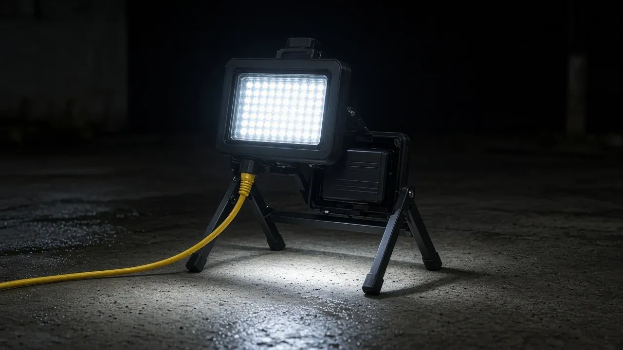
Rule of thumb: if the shift exceeds 3 hours and the crew needs the high setting whose published runtime is 3 hours on one XC5.0 pack, one pack does not finish the shift. A 9-hour shift is 9 / 3 = 3 of those packs in sequence, or the AC port. Three packs is the rotation count only when a charged pack is already waiting. The page does not publish recharge time, so the charger queue is still an open number. The power station sizing guide is where that light’s watts join the rest of the load list. IP54 on this page is a manufacturer statement for this model; the IP rating guide is how to read the code without turning it into an outdoor warranty.
What the wrong figure costs
The hidden account is packs, extra fixtures, and rework, not a dollar price.
On the Milwaukee high-mode line, a 9-hour shift at the published 3-hour runtime consumes three XC5.0 pack cycles instead of one. The low setting stretches one pack toward 30 hours and does not keep the 4,500 lm claim. Teams that “solve” a wide beam by stepping up to high mode pay that pack count every shift.
A 120° contour at 2.00 m is 6.93 m across. A 0.60 m panel sits in a small part of it. The usual field response is a second lamp aimed at the panel. That second lamp is a second load on the same supply the sizing guide has to carry.
A CRI ranked across the 5000 K reference change, or a missing R9 when reds and yellows have to be separated, shows up as a wrong termination and a rework hour. The fact sheet’s visual check is cheaper than that hour when it happens before the purchase, on the actual insulation colors, under the lamp that will be bought.
Put the delivered-lumen line, the contour diameter, the CCT beside the CRI, and one row per supply into the comparison sheet from the buying guide. Leave a cell blank when the document does not state it.
Method and sources
Numbers in the worked examples are products of the OSHA table value, the NIST conversion factor, and the stated area or the stated beam geometry. tan(30°) and tan(60°) are the ordinary trigonometric values 0.577350 and 1.732051. The Milwaukee figures are that model’s product page, read on 20 October 2026, and they stop where that page stops. LM-79-08 section 5.0 is cited from the 2008 method in a public filing; LM-79-24 was not substituted for it. The IES beam-angle page returned HTTP 403 to a direct download and was read from the public glossary page on the same date. Photographs are illustrations of a tripod lamp, a terminal box, and a cord-plus-battery arrangement. They are not the cited Milwaukee model and they are not measurements.
Sources and versions
- SI units , National Institute of Standards and Technology Supports: The SI is the measurement system used for the lumen and the lux. The numeric footcandle conversion is taken from the NIST conversion table cited next.
- NIST Guide to the SI, Appendix B.8, conversion factors , National Institute of Standards and Technology Supports: Footcandle to lux, and lumen per square foot to lux, are both 1.076391 × 10^1. The international foot to meter factor is listed as 3.048 × 10^-1.
- 29 CFR 1926.56 Illumination , Occupational Safety and Health Administration Supports: Table D-3 minimum illumination in foot-candles, including 3 for field maintenance areas, 5 for general construction area lighting, 10 for general construction plant and shops, and 30 for first aid stations, infirmaries and offices.
- beam angle , Illuminating Engineering Society Supports: Beam angle is the angle between the two directions at 50% of maximum intensity in a plane through the nominal beam centerline. Asymmetric beams are reported in two planes. Some older practice used 10% of maximum.
- ENERGY STAR Program Requirements for Lamps, Version 2.0 , U.S. Environmental Protection Agency Supports: Beam angle definition citing ANSI C78.379-2006: full angle between opposite directions at 50% of center-beam intensity, measured in at least two rotational planes. CRI definition citing 10 CFR 430.2.
- LED Color Characteristics fact sheet, PNNL-SA-84900 , U.S. Department of Energy, Building Technologies Program Supports: January 2012 fact sheet: CRI averages eight test colors; interior guidance of 70s, 80s and 90s is a rough scale; CRI at very different CCTs should not be compared; the reference changes at 5000 K; R9 is supplemental; critical color work needs a visual check.
- IES LM-79-08, section 5.0, public filing , Illuminating Engineering Society, text filed in a USPTO public record Supports: The 2008 approved method: measure after stabilization; typical time from 30 minutes for small integrated LED lamps to 2 or more hours for large luminaires; stability when three readings over 30 minutes, 15 minutes apart, vary by less than 0.5% in light output and electrical power. Later editions exist; their full text was not used here.
- M18 ROVER Dual Power Triple-Panel Flood and Area Light , Milwaukee Tool Supports: Published page for this model: 4,500 lumens on high with an M18 XC5.0 pack for 3 hours; up to 30 hours on the lowest setting with that pack; AC port described as all-day runtime; 120 V AC extension cord or M18 battery; IP54; 9 ft drop statement. No CRI, CCT or beam angle in the passages read.
Next steps
Portable Work Lights: A Buying Guide for Outdoor Teams
How outdoor teams can compare portable work lights: lumens vs lux, beam pattern, runtime claims, mounting, protection ratings, plus a supplier comparison sheet.
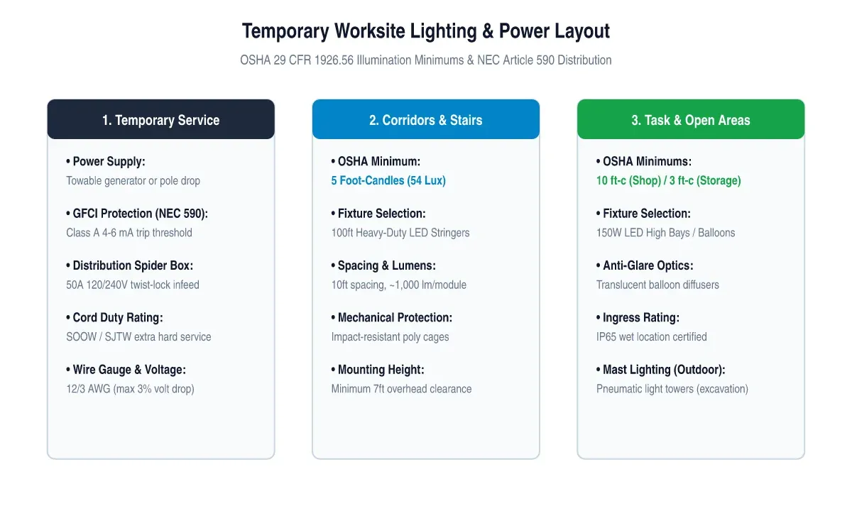
Temporary Construction Lighting: OSHA Requirements and Worksite Power
A technical guide to temporary construction lighting: OSHA minimum illumination standards (29 CFR 1926.56), string lights vs high bay vs balloon diffusers, GFCI distribution, and generator sizing.
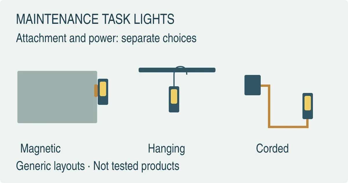
Maintenance Task Lights: Magnetic, Hanging or Corded
Choose a magnetic, hanging or corded maintenance light by its mounting point, cable route and documented limits. Includes three manual examples and a buyer checklist.
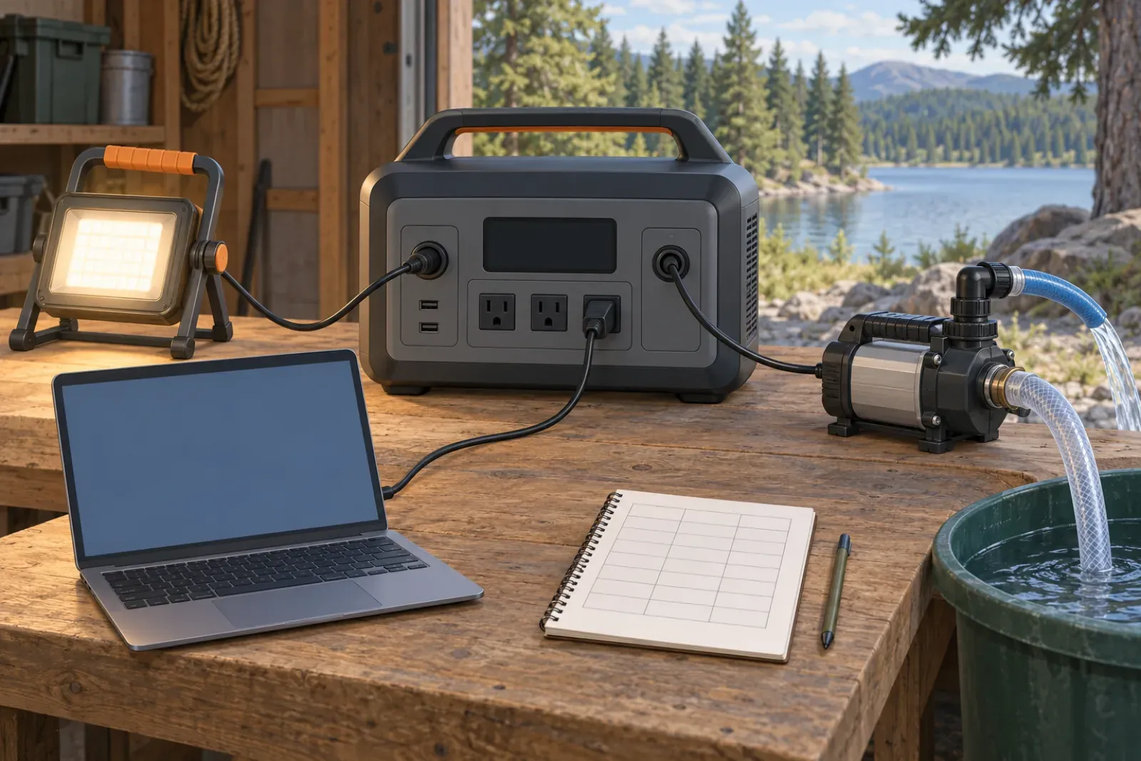
How to Size a Portable Power Station for Outdoor Work
Size a portable power station for outdoor work: list loads, check continuous and surge watts, estimate watt-hours with stated assumptions, and verify charging.